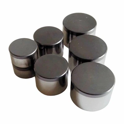
How Should PDC Cutters Be Selected for Interbedded Formations?
Introduction
There are several considerations to take into account when choosing a PDC cutter for drilling through interbedded formations. It will often not be sufficient to simply select the most abrasion or shock resistant PDC grade available. As mudstones, sandstones and shales alternate, the drill bit will be subjected to varying degrees of abrasivity and shock, potentially resulting in torque and RPM variation, increased stick slip, cutter chipping and differential wear.
By considering the degree of abrasivity, degree of shock experienced at the cutter, cutter position, geometry, bit hydraulics and past drilling experience, improved consistency in ROP and bit life can often be achieved. This article outlines some of these key points and describes how past field data can be used to benchmark alternative PDC cutters.
Four Common Field Challenges
- Stick-slip vibration and premature chipping
As mudstone, sandstone and shale beds change, the bit will encounter a range of formation strengths. This can lead to varying amounts of torque and RPM, and hence an increased propensity for stick slip. Under some circumstances, this can place additional dynamic load(s) on the PDC cutters and result in chipping or loss of diamond.
- Unstable rate of penetration (ROP) and unpredictable footage
Variation in the properties of the rocks being drilled, and/or progressive deterioration of the PDC cutters will influence the rate at which the bit can progress through the formation. Footage per bit can therefore be difficult to forecast and plan for.
- Rapid wear and mismatched performance grades
Depending on the proportion and type of sandstone and shale being drilled, the diamonds on the PDC cutter can be consumed more quickly than anticipated. If only the abrasion resistant grades of PDC cutters are considered, the degree of shock experienced may prove detrimental. Similarly, if only the shock resistant grades are chosen, excessive wear may limit the life of the bit.
- Non-productive time (NPT) and cost pressure
If the PDC bit deteriorates before the desired footage has been made, the rig will need to be tripped in order to inspect and possibly change the drill bit, and alter the drilling program. The cost implications of this will extend beyond the initial purchase price of the bit and its constituent PDC cutters.

From Formation Evaluation to PDC Cutter Selection
1. Gather information on the formation, working conditions and prior cutter failures
The following categories of data should be obtained to enable a sound starting point for selecting PDC cutters:
- Formation: lithology mix and proportions of mudstone, sandstone, shale, and interbedded streaks.
- Operating conditions: changes in rock hardness and abrasiveness, WOB, RPM, flow rate, and other available drilling parameters.
- Failure history: whether dull cutters show chipping, spalling, or relatively uniform wear; which cutter positions fail first; and the relevant back-rake, layout, and hydraulic conditions.
Naturally, none of this can be assessed by looking at the dull bit alone, which is why the drilling parameters and history should also be consulted.
2. Select the optimum balance of PDC abrasion and shock resistance based on cutter position
Primary cutters carry the main cutting load. Their selection should account for formation transitions, WOB, RPM, cutter position, and bit structure. Where interbedded formations involve distinct shock or torsional fluctuations, evaluate grades with stronger impact resistance while retaining suitable wear capability. Do not assume that the highest wear-resistance grade is automatically the best choice.
Gauge cutters also require attention to sidewall contact and wear. Flat or chamfered profiles should be selected in conjunction with cutter layout, back-rake angle, and the overall bit design.
3. Determine the required PDC cutter size from the bit design
Sizes such as 13 mm and 16 mm are candidates in certain conventional onshore bit designs, but neither is a universal standard. Actual diameter and height should follow bit geometry, cutter-position constraints, cutting structure, and drilling conditions. Other dimensions may be required for specialized designs. Customized dimensions should be confirmed against the customer's drawing and agreed technical specifications.
4. Consider the bit's hydraulic arrangement
The removal of rock fragments from the BHA and prevention of overheating of the PDC cutters will be aided by ensuring sufficient flow-rate and correctly placed nozzles and junk slots. Insufficient flow and inadequate placement of these features can give rise to re-cutting of cuttings, build up of material on the face of the bit, and high cutter temperature. Any proposed changes to the PDC cutters should therefore be assessed in light of the existing (or modified) bit hydraulics.
5. Ensure batch-to-batch consistency and confirm inspection protocol

It is in the interests of bit manufacturers to maintain close dimensional and property tolerances within and between production runs of PDC cutters, to minimize the effects of assembly variance on bit performance in the field. Based on the particular PDC product range and the level of certification offered by the manufacturer, some or all of the following features may be inspected:
- Cutter diameter and height;
- Chamfer dimensions and profile;
- Diamond-table thickness and surface condition;
- Diamond-table-to-substrate bond-area quality;
- Batch identification and traceability.
Clearly, these should be conducted in accordance with the relevant technical specification and the manufacturer's facility for performing the tests. It is not appropriate to assume that any of the above features are 'certified' unless evidence of this can be obtained.
6. Determine an appropriate cost per meter
Comparing cutters solely by unit price does not capture total drilling cost. A consistent cost-per-meter calculation may include bit-related costs, trip-related costs, and other agreed cost items divided by actual drilled footage:
Cost per meter = (Bit-related cost + Trip-related cost + Other included costs) ÷ Drilled footage
For a fair comparison, keep the cost boundaries, interval, formation, and operating parameters consistent. Clarify whether rig time and other indirect costs are included, and use actual footage rather than planned footage.
Selection Direction by Formation and Operating Condition
| Formation / operating condition | Primary concern | Initial selection direction |
| Soft-to-medium interbedded mudstone and sandstone with noticeable stick-slip | Torque fluctuation and possible impact-related chipping | Balance impact resistance and wear performance; review cutter layout and drilling parameters |
| Abrasive sandstone or shale with predominantly uniform wear | Faster diamond-table wear and gradual ROP decline | Evaluate higher wear resistance; verify cooling, cleaning, and bit design |
| Interbedded layers with notable shock or impact loading | Cutter chipping or localized material loss | Evaluate impact-resistant grades alongside cutter position, back-rake, WOB, and RPM |
| Multi-field or multi-bit inventory planning | Different requirements across wells and fields | Standardize size-and-grade combinations around recurring bit designs and track performance by field |
Field Trials and Acceptance Criteria
Where feasible, a field trial should be undertaken of the proposed PDC cutter(s) in a suitable interval or field. Key metrics to monitor would be:
- ROP: compare average performance and stability across comparable intervals, not brief peak rates.
- Footage per run: record actual footage and the number of trips.
- Failed cutter locations and patterns: identify positions and distinguish chipping, localized material loss, and uniform wear.
- Overall dull-bit condition: document the condition of the bit after the run.
- Cost per meter: calculate using consistent cost boundaries.
Following the field trial, efforts should be made to retrieve and image the relevant worn and failed cutters. These can then be compared with the original premise on which the PDC grade was selected, and any modifications made accordingly.
Information Checklist Before Requesting PDC Cutter Selection
The following list of information will facilitate the supplier's ability to comment on the likely applicability of their PDC range. The final decision will still be dependent on the bit design and field conditions.
| Information to provide | Why it matters |
| Formation type, lithology mix, and abrasiveness | Helps characterize wear and impact conditions |
| Cutter diameter, height, chamfer, and current grade | Confirms dimensional and performance requirements |
| Bit type, layout map, and cutter positions | Clarifies loading and geometric limits by position |
| WOB, RPM, flow rate, and operating parameters | Provides context for mechanical and hydraulic evaluation |
| ROP, footage per run, and dull-bit records | Supports comparison and failure analysis |
| Photos or samples of failed cutters, if available | Helps assess failure location and pattern alongside operating data |
Henan Deqin New Material Co., Ltd. (DQ Diamond) specializes in diamond superhard materials, including PDC Cutters and PCD Inserts. For onshore drilling and industrial applications, dimensions, geometries, and performance specifications can be tailored according to customer drawings, operating conditions, and mutually agreed technical specifications.
If you are evaluating PDC cutter grades or dimensions for a specific formation or bit design, share your target specifications, operating parameters, or dull-cutter observations with our team for a technical discussion.

FAQ
Q: What can cause PDC cutter chipping?
A: Potential contributors include impact loads, formation transitions, cutter exposure, bit layout, and operating parameters. Review drilling records and dull-bit inspection together rather than assuming a single cause from visual damage alone.
Q: How does stick-slip vibration affect PDC cutters?
A: Stick-slip creates fluctuations in rotary speed and torque and can increase cyclic mechanical stress on the cutting structure. The actual effect depends on vibration severity and duration, bit design, and drilling parameters.
Q: How should wear-resistant and impact-resistant PDC cutters be selected?
A: Identify the dominant failure pattern first. Give greater attention to wear resistance when abrasive wear dominates, and to impact resistance when shock-related chipping dominates. Also review cutter position, bit layout, and operating conditions.
Q: What PDC cutter size should be used for onshore oil and gas drilling?
A: Size should be determined by bit geometry, cutter-position constraints, cutting structure, and operating conditions. 13 mm and 16 mm may be candidates for selected conventional designs, but they are not universal standards.
Q: How can PDC cutter performance be evaluated in the field?
A: Compare ROP stability, footage per run, dull-bit condition, failed cutter locations and patterns, and cost per meter under comparable operating conditions and consistent cost definitions.